- Fri 25 June 2021
- Teaching
- #demo, #teaching, #electricity, #basic-circuits, #youth, #4-h
If you've known me for any period of time, you probably already know that I grew up participating in my local 4-H program. I was a Cloverbud member before I could be a regular member, meaning I spent about twelve years in the program. Ten of those years were spent raising hogs, and a few were also spent participating in various leadership roles.
I spent a year as my community-club's secretary, two years as president; and I even served as vice-president and even president of my county's teen leadership club. It was a great experience, and I learned so much about myself during all of those adventures. In my last two years as a member, I was able to attend the Idaho state "Teen Conference" as it was called at the time. It was (and is) a statewide event held on the University of Idaho's campus to give high-school students the opportunity to explore a college campus, learn new leadership skills, and connect with peers from around the state.
In the past few years, I've had the extreme pleasure of supporting the conference (now called the State Teen Association Convention - or STAC for short) as a college staff member, but this year I was able to participate as a chaperone, and what's more, I was able to co-lead a workshop during the conference. What did I lead? Oh! A workshop covering electricity and the electrical power grid; of course!
I worked with a few colleagues from Schweitzer Engineering Laboratories to create a workshop to cover a few interesting topics about the grid. But, if you know me, you know I much prefer hands-on exercises than any presentation. So I spent a little too much time working on creating a couple of demo boards; seven in total.
The Demos:
I made two sets of three boards, and a single stand-alone board. They were all to basically show:
- Basic circuit: generation/source, transmission, and load
- Overloading circuit: multiple incandescent lights and a USB charger
- "Breaker" demonstration
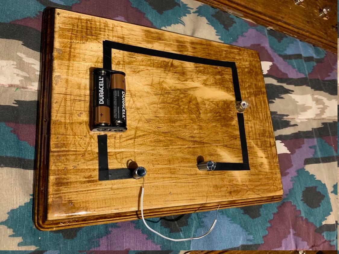
I made three of the basic circuit, ultimately to make a point about what an electrical fault might appear as, and how repairing it might be possible. It was basically constructed with a AA battery pack, a few spring terminals, and a single incandescent T-10 socket/bulb. With this model, we're able to explain the basics of an energy source, energy transmission, and an energy sink (load). What made this fun, was that we could go around once the students had their little power system running and create a "fault" by cutting the wire between the spring terminals. Then we could instruct the students to fix their system and leave them to their own devices (and a few odd assorted materials).
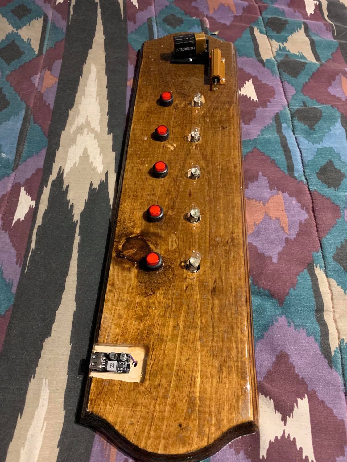
I also made three of the overloading circuit. This one was, by far, my favorite. You see, these boards are set up with 5 separately controlled T-10 sockets, each with their own ON-OFF latching pushbutton. There's also the matter of a USB phone charger connected at the "far end". The whole thing is powered by a single 9V battery, connected to the rest of the circuit by a single 1-ohm power resistor. This all means that as each of the incandescent lights are turned on (being as they're all connected in parallel) the voltage across the power resistor will continue to drop. The USB charger circuit is rated for some 6-24VDC (approximately). Meaning that when the voltage input drops below the rated minimum (6V) the supply will cease to function. That means that the system will quite easily overload to the point of failure. This was a great example for the students, because it allowed them to truly play with the system until they can get a sense about how the system can be "loaded down". The point here was just to share with students just how the power system can theoretically be overloaded, and how that's not good for any of the consumers. Pretty cool to see in action!
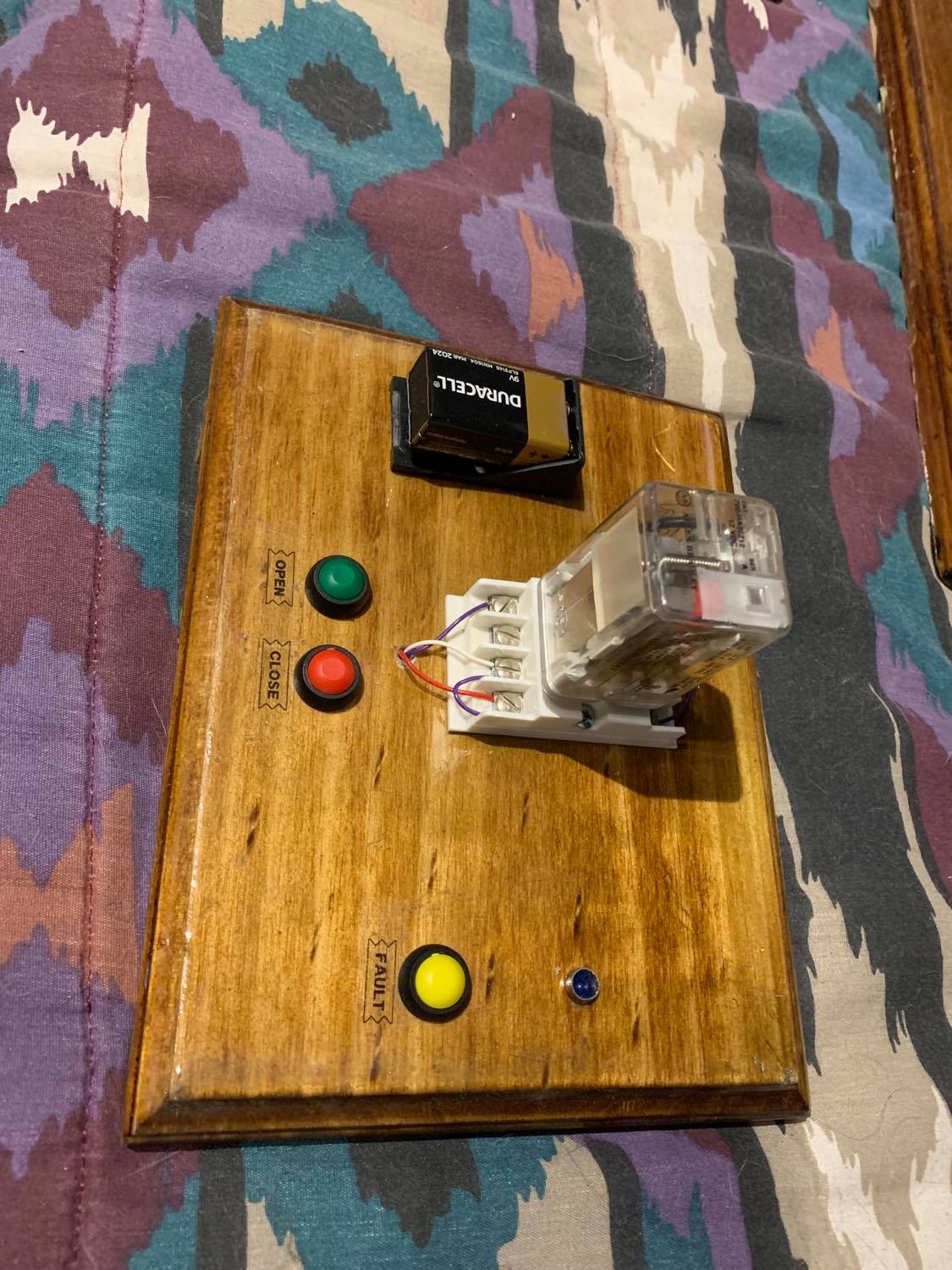
Finally, I built a single board (on a whim, I might add) to demonstrate how a breaker acts (effectively) as a latching switch. I used a simple ice-cube relay to act in this capacity, and to be controlled by a few simple push-buttons. One button (red, of course, to match the electrical industry standard) was used to close the breaker. One button (green -just as the red- matching the industry standard) to "open" the circuit, and finally a simple button offset from the others, and labeled to indicate a fault. It's quite simple, really; both the fault and open switches effectively create a simple dead-short so as to reduce the voltage across the relay coil to the point of loosing the magnetic field, and falling open. However, from the student's perspective, it all looks and feels real. It seems that the "breaker" is responding to commands to open or close, and that it responds to a fault by opening to protect itself and the system. Lastly, I should note, there is a single blue LED in this circuit, too, just to indicate whether the circuit is energized or not.
The Results:
The demo boards were a pretty good success. The 4-H delegates really seemed to enjoy them, and got engaged right away with them, seemingly having great fun playing with them. I'm very excited to say that they'll be even more useful in the hands of the SEL K-12 outreach program. My colleague will be taking them to play even more, and hopefully continue using them for a variety of great, hands-on exercises.
I've been thinking more and more about some other activities that I might be able to "construct" in hardware to simplify the educational experience and make them more accessible for others moving forward. One that I'm really looking towards is a simple power-system protection system. This where students can actually make decisions to open breakers, shed load, and increase generation, all to respond to various electrical phenomena, and all actions being accounted for by an automated system capable of making real changes to the system to show what happens after each scenario.
A little vague description, I know... But that's because I hope to actually build this thing, and show it off in the relatively (relatively) near future!